Technical Resources

Design Guides & Technical Resources

Everything architects, engineers, and developers need to design with modular construction. Download specifications, BIM families, technical guides, and sample drawing sets — free resources maintained and updated quarterly by our in-house engineering team.

Downloads

Design Resources

Free technical resources to help you design, specify, and deliver modular buildings. All content is authored by our engineering team and updated quarterly to reflect the latest standards and product developments.

MODURA BIM Families

Revit families (.rfa), IFC models, and ArchiCAD objects for all MODURA standard module types. LOD 350 with parameter-driven dimensions, UK and European content libraries. Updated quarterly to reflect product changes. Free download — no registration required for basic families. Full library access with email registration.

FREE Download

Technical Specification Library

NBS Chorus specification clauses ready for insertion into your project specification. BBA and BOPAS certification documents. Acoustic test reports to BS EN ISO 16283. Fire test evidence to BS EN 13501. Thermal performance data sheets. Embodied carbon assessments per EN 15978. All documents maintained current with regulatory changes.

FREE Download

Drawing Templates

General arrangement plans, module layout sheets, MEP coordination drawings, foundation interface details, and connection detail library. Available in DWG and PDF formats with standard MODURA title blocks. Includes a sample project drawing set (50-unit residential) showing the complete documentation package for a real completed project.

DWG + PDF

Sample Specifications

Five worked example specification sets, each covering a complete building type: multi-family residential (Spec A), hotel (Spec B), office (Spec C), healthcare (Spec D), and education (Spec E). Each includes structural loading assumptions, fire strategy, acoustic targets, MEP specification, and finishes schedule — ready to adapt for your project.

5 Spec Sets

Design Rules

Design for Manufacture (DFM) Rules

These ten DFM rules capture 15 years of modular manufacturing experience. Following them from the start of design avoids costly redesign later. Modules that comply with these rules flow through the factory with predictable quality, cost, and programme.

Rule Requirement Reason
Module width Standard: 3.6m, 4.0m, 4.2m. Maximum: 4.5m Road transport limit. Wider modules require escort vehicles and route-specific permits, increasing cost and lead time.
Module length Standard: 9m, 12m, 14m. Maximum: 16m Transport and cranage constraints. Longer modules reduce module count but increase weight, requiring larger cranes.
Module height (internal) Minimum 2.4m finished floor to ceiling. Standard 2.55m Building regulations minimum plus allowance for MEP services distribution within the ceiling void.
Structural grid Align module joints with the structural grid. Avoid columns inside module footprints The module joint IS the structural grid line. A column inside a module forces a split-module design, doubling complexity.
Service risers Locate in dedicated riser modules or at module junctions. Vertical continuity is essential Pre-fabricated risers are assembled and pressure-tested in the factory before dispatch. Site connections plug-and-play.
Wet areas Locate bathrooms and kitchens at module perimeter for drainage falls. Avoid central wet areas Drainage must gravity-feed to the riser. Central wet areas require pumped drainage, adding cost and maintenance liability.
Party walls Double-skin construction with 50mm cavity minimum. No direct structure-borne path between modules Acoustic isolation target: DnT,w + Ctr ≥ 45dB. Achieved through complete structural separation between adjacent modules.
Ceiling services Allow 150mm minimum ceiling void for MEP distribution. 200mm preferred where ventilation ducts are routed MEP first fix is pre-installed in the factory ceiling void. Inadequate void depth forces on-site rework and compromises quality.
Floor build-up 25mm raised access floor or screed above the structural floor cassette Provides the service distribution zone plus acoustic isolation from the floor above. Pre-installed in the factory.
Facade attachment Design facade as an independent rain screen with thermal break at module edge Accommodates differential movement between modules. Maintains thermal continuity and weatherproofing across module joints.
Parameters

Recommended Technical Parameters

Industry-proven technical parameters for five common building types. Use these as starting points for your project brief. All parameters are based on UK and European regulatory requirements and can be adjusted for local codes.

Parameter Residential Hotel Office Healthcare Education
Floor-to-floor height2.9–3.0m3.0–3.3m3.3–3.6m3.6–4.2m3.0–3.3m
Structural steel gradeS275–S355S275–S355S355–S460S355S275–S355
Fire resistance60 min60–90 min90 min120 min60–90 min
Acoustic DnT,w+Ctr≥45dB≥50dB≥45dB≥50dB≥45dB
Thermal U-value (wall)0.18 W/m²K0.18 W/m²K0.18 W/m²K0.15 W/m²K0.18 W/m²K
Design life60 year60 year60 year60 year60 year
Ventilation strategyMVHR / MEVMVHR + ACMVHR + AC/VRFHEPA MERV 15MVHR
Lessons Learned

Common Design Mistakes to Avoid

After 500+ projects and 10,000+ modules, we have seen the same mistakes repeated. These six are the most frequent and the most expensive to fix. Design around them from day one and your project will run smoothly.

Exceeding Transport Limits

Designing modules that exceed transport limits. Check maximum dimensions (4.5mW × 16mL × 3.6mH for road) before finalizing your layout. Wider modules need escort vehicles which increase cost. Longer modules need heavier cranes which increase cost. Design within standard envelope dimensions unless the programme benefit demonstrably outweighs the logistics premium.

Structural Elements Inside Module Footprint

Placing columns or shear walls inside module footprints. Columns and shear walls should ALWAYS align with module edges. A column inside a module forces a split-module design, doubling the module count and joint complexity. The module joint IS the structural grid — align all vertical structure with it from the earliest concept stage.

Assuming Site Tolerances Match Factory

Assuming site tolerances match factory tolerances. Module-to-module: ±2mm. Foundation: ±5mm. Allow a 20mm tolerance zone at the module-to-foundation interface. Do NOT design zero-tolerance connections between factory-produced modules and site-poured foundations. Every interface between factory work and site work needs an adjustable connection detail with defined tolerance accommodation.

Forgetting About Cranage

Check four things before locking the site layout: Is there crane access on all four sides of the building? Can the crane reach the furthest module at the required working radius? Is the ground bearing capacity adequate for the fully-loaded mobile crane? A mobile crane needs a minimum 15m × 15m hardstanding area. If the answer to any of these is no, the logistics plan needs to change.

Over-Specifying Unique Module Types

Each unique module type requires a separate jig setup on the factory production line. Target ≤8 unique module types per project. Use repeat module types with different internal fit-outs — kitchens, bathrooms, and finishes can vary without changing the structural module chassis. Every unique structural module type above 8 adds approximately one week to the production programme.

Late Changes After Production Starts

Changing room layouts after Station 9 (finishes) costs 5–10× the original change. ALL design decisions should be locked no later than Station 3 (steel frame). Request a factory sample module if you are unsure about finishes or layouts — seeing a full-scale physical module is far cheaper than changing 100 modules after they are built.

Compatibility

File Formats We Accept

We work with industry-standard file formats across all design and engineering disciplines. If your team uses a format not listed here, contact our BIM team — we can accommodate most software ecosystems through IFC interoperability.

  • Architectural: Revit (.rvt), IFC 2×3 / IFC 4, DWG, SketchUp (.skp)
  • Structural: Revit, Tekla Structures, IFC, DWG
  • MEP: Revit with Systems, IFC, DWG
  • Point Clouds: .e57, .rcp, .pts (for existing building retrofit and refurbishment projects)
  • Specifications: NBS Chorus, Microsoft Word, PDF
  • Programme: Microsoft Project, Asta Powerproject, Primavera P6
  • BIM Data: COBie, IFC with property sets aligned to ISO 19650

All files are handled under NDA. We maintain ISO 19650-compliant Common Data Environment (CDE) for every project — your data is secure, version-controlled, and accessible to authorized team members only.
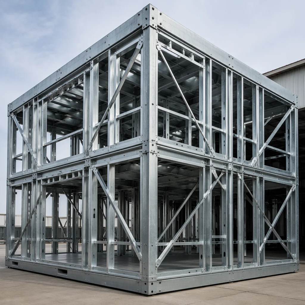
MODURA BIM coordination workspace showing Revit model with structural, architectural, and MEP disciplines overlaid

Download the Complete Design Guide

Enter your email to receive our 60-page Technical Design Guide with sample drawing set and BIM family download link. Includes all DFM rules, parameter tables, connection details, and specification templates.