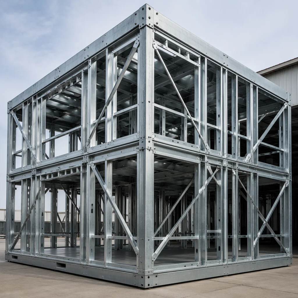
A modular building experiences forces that conventional structures never see: the dynamic shock of transport, the concentrated stresses of a crane lift, the multi-axis loads of stacking. Our structural engineering team has developed proprietary analysis methods that account for every load case across the module's entire lifecycle — from factory floor to 40-storey service.
Every MODURA module is designed and verified against all applicable Eurocodes, with five distinct load cases analysed before fabrication drawings are released.
| Parameter | Standard | Specification |
|---|---|---|
| Design Code | EN 1990 | Basis of structural design, 60-year design working life, Consequence Class CC2/CC3 |
| Actions on Structures | EN 1991 | Imposed loads 2.0–5.0 kN/m², wind to EN 1991-1-4, snow, thermal, and accidental actions |
| Steel Design | EN 1993 | Cold-formed to EN 1993-1-3, hot-rolled to EN 1993-1-1, grades S275–S460 |
| Composite Design | EN 1994 | Steel-concrete composite floors and transfer structures, shear stud design |
| Seismic Design | EN 1998 | Ductility Class DCM/DCH, q-factors per national annex, capacity design |
| Fire Design | EN 1993-1-2 | Structural fire engineering, critical temperature method, up to REI 120 |
| Execution | EN 1090-2 | Execution Class EXC3, weld quality to ISO 5817 Level B, full traceability |
| Load Case | Load Factors | Design Condition | Governing Limit State |
|---|---|---|---|
| LC1 — Factory Lift | Dynamic factor 1.5 × SW | Module lifted from casting bed to transporter | Local buckling, web crippling at lifting points |
| LC2 — Transport | ±0.5g horizontal, ±0.3g vertical | Road transport over 500+ km, braking and cornering | Fatigue, racking deformation, connection integrity |
| LC3 — Crane Erection | Dynamic factor 1.6 × SW + 0.5 kN/m² wind | Mobile or tower crane lift at up to 12m radius | Global stability, lifting frame design, sling angles |
| LC4 — Stacking | 1.35Gk + 1.5Qk per EN 1990 Eq 6.10 | Up to 12 modules stacked, temporary and permanent | Bearing, column continuity, inter-module shear transfer |
| LC5 — In-Service | Full ULS & SLS combinations to EN 1990 | Permanent occupancy, wind, snow, seismic, thermal | All ULS verifications + SLS deflection < span/360 |
Before any steel is cut, every module undergoes full finite element analysis (FEA) using ANSYS, Robot Structural Analysis, or Tekla Structural Designer. We model the complete module geometry — cold-formed wall studs, hot-rolled edge beams, corner posts, and diaphragm action of sheathing boards — under all five load cases simultaneously.
Our structural deliverables package provides the complete engineering narrative: from concept stability assessment through to full fabrication drawings with weld maps and bolt schedules. Every calculation is independently checked by a Chartered Structural Engineer.
Beyond standard modular design, our team brings deep expertise in four specialist areas that unlock taller, more complex, and more resilient modular buildings.
Light-gauge steel framing to EN 1993-1-3 with optimised section profiles (C- and Z-sections, Sigma studs). Our in-house buckling analysis covers local, distortional, and global modes, with stud spacing and bracing optimised per module load case. Typical steel weight savings of 12–18% compared to prescriptive design through rational analysis.
For buildings above 12 storeys or with open-plan ground floors, hot-rolled steel transfer structures (UC columns, UB/ASB beams) carry modular loads to foundations. Our composite design to EN 1994 achieves column-free spans up to 12m, enabling retail, lobby, or parking at ground level with modular construction above.
Full seismic design to EN 1998 with capacity-designed ductile connections. We use pushover analysis (N2 method) and, for taller or irregular structures, nonlinear time-history analysis (NLTHA) to verify performance. Inter-module shear connections are detailed to yield before column buckling, delivering ductile failure modes with behaviour factors q ≤ 3.0.
Alternative load path analysis in accordance with EN 1991-1-7 and UFC 4-023-03. Each module connection is assessed for its ability to bridge over a notionally removed column or loadbearing wall. Where tying resistance alone is insufficient, we detail key element design with enhanced connection capacity to prevent disproportionate collapse.
All structural steel is sourced from ISO 9001-certified mills with full material traceability and 3.1 certification to EN 10204.
| Application | Grade | Standard | Min. Yield | Typical Sections |
|---|---|---|---|---|
| Cold-Formed Wall Studs | S350GD + Z275 | EN 10346 / EN 1993-1-3 | 350 MPa | C100–C200 lipped channels @ 400–600mm c/c |
| Cold-Formed Floor Joists | S390GD + Z275 | EN 10346 / EN 1993-1-3 | 390 MPa | C200–C300 lipped channels @ 400mm c/c |
| Hot-Rolled Edge Beams | S355J2 | EN 10025-2 | 355 MPa | UB 203–356, PFC 200–300 |
| Hot-Rolled Corner Posts | S355J2 / S460M | EN 10025-2/4 | 355–460 MPa | SHS 120–250 × 8–12.5mm wall |
| Transfer Beams & Columns | S355J2 / S460M | EN 10025-2/4 | 355–460 MPa | UC 254–356, SHS 250–400 |
| Base / Holding-Down Bolts | Grade 8.8 / 10.9 | EN 15048 / EN 14399 | 640 / 900 MPa | M20–M36, preloaded where required |
Share your building concept with our structural team. We provide a technical feasibility review, indicative module layout, and structural system recommendation within 10 working days.
Get Started