Ask a modular contractor where a multi-storey project loses its schedule advantage and the answer is rarely the modules. It is the shaft. A stair core and an elevator shaft are the only two elements of a building that cannot be manufactured as a finished, tested room and set into place, because they are voids that have to run uninterrupted from foundation to roof while everything around them arrives in 15-tonne pieces. Get the interface wrong and the elevator installer inherits a shaft that is 40 mm out of plumb over eight storeys, and the handover date moves by a quarter.
This article sets out how a vertical transport core is actually built in a modular programme: what can be prefabricated and what cannot, the dimensional tolerances that determine whether a lift will run at contract speed, the two compliance pathways for a lift shaft that is not a traditional concrete box, and the sequencing decisions that decide whether the elevator is commissioned before or after the building is finished. The numbers below are the ones we use to price and schedule cores on projects from two to six storeys, where the majority of modular healthcare, senior living and mid-rise residential work sits.
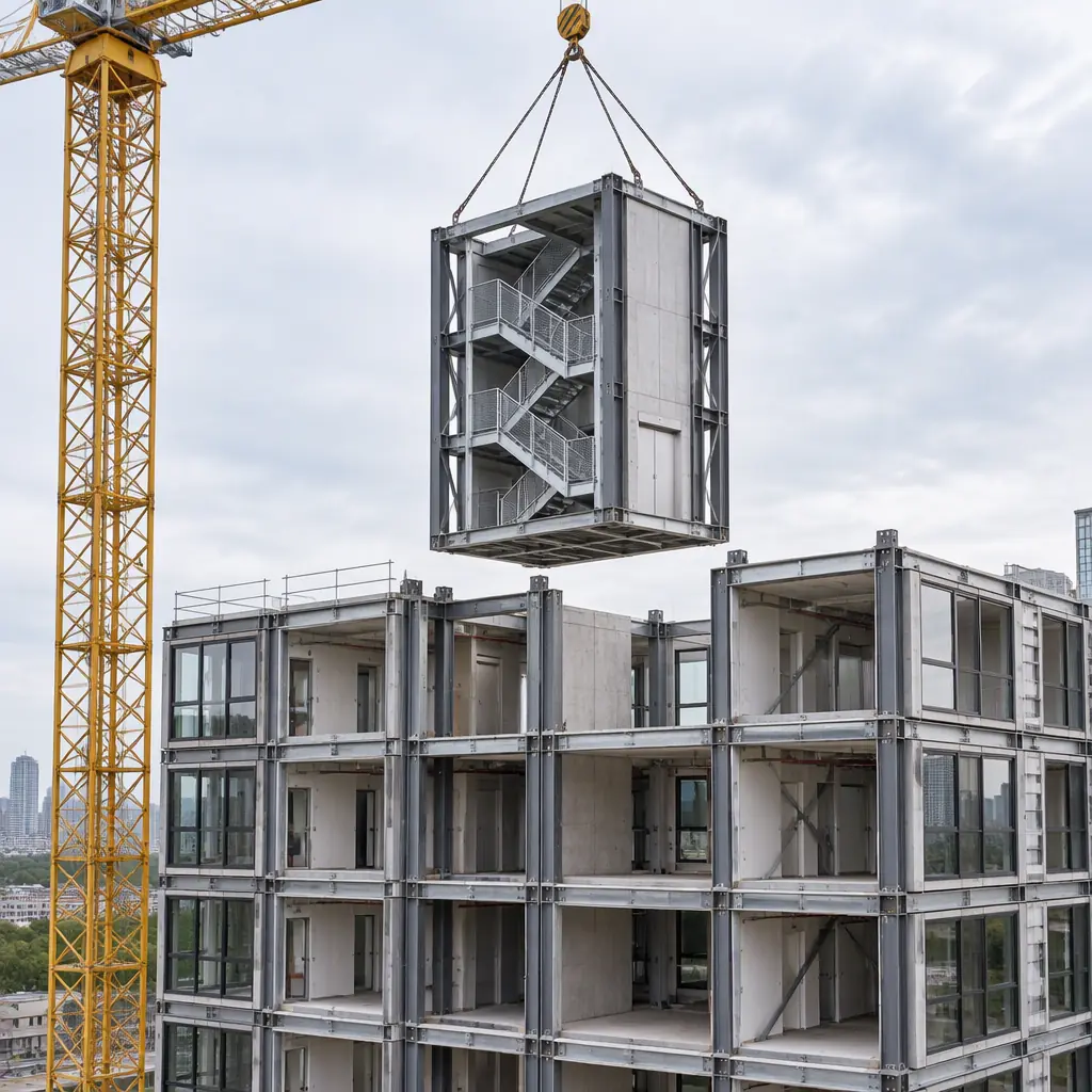
What a Vertical Transport Core Actually Is in a Modular Building
A vertical transport core is the non-repeating part of the building. It contains the stair flights, the lift shaft or shafts, the lobby at each level, and the risers that carry sprinkler mains, drainage stacks and electrical distribution vertically through the structure. In a conventional building it is a cast-in-place concrete box built first, with the floor plates tied into it. In a modular building the core is one of three things, and the choice is made at concept stage because it changes the structural system, the crane plan and the fire strategy simultaneously.
| Core type | How it is built | Storey range where it makes sense | Schedule effect versus traditional core |
|---|---|---|---|
| Cast-in-place concrete core | Site-built reinforced concrete, slipform or jumpform; modules tie into cast-in embeds | 4 storeys and above; mandatory in many high-rise jurisdictions | Core is on the critical path before module setting can start at upper levels |
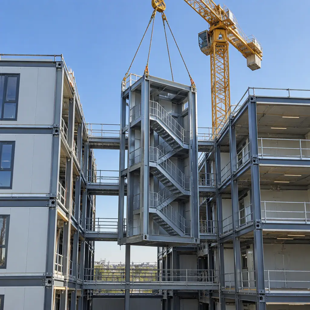
| Prefabricated steel core module | Volumetric steel-framed core with stair flights, landings and shaft walls factory-fitted; delivered as 1-2 modules per storey | 2 to 6 storeys | Core and modules arrive on the same shipping schedule; no separate site trade |
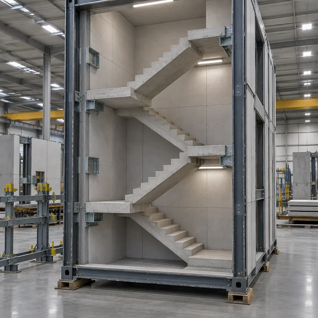
| Hybrid core | Precast stair flights and landings inside a steel-braced frame, with fire-rated board shaft lining installed on site | 3 to 8 storeys | Faster than cast-in-place, less factory content than a full volumetric core |
The cast-in-place core is the default because it does two jobs at once: it carries the lateral load, and it provides the fire separation that a stair and lift shaft requires. A prefabricated steel core takes the first job only if it is braced and analysed as part of the stability system, and takes the second job only if the shaft lining is a tested assembly rather than a nominal board lining. That distinction is where most of the technical risk in a modular core sits, and it is the reason a steel core is cheaper on a four-storey senior living building and inappropriate on a twelve-storey residential tower without an independent stability solution.
Prefabricated Stair and Lift Core Modules, What Goes in the Factory
A prefabricated core module is not a steel box with a staircase dropped into it. On the units we produce, a single core module for one storey carries the following scope before it leaves the factory, and each item on that list is a trade that does not appear on the site programme.
- Stair flights and landings: precast concrete or steel pan flights with the going, rise and nosing already set to the code geometry for the destination market, handrails and balustrades fitted and load-tested.
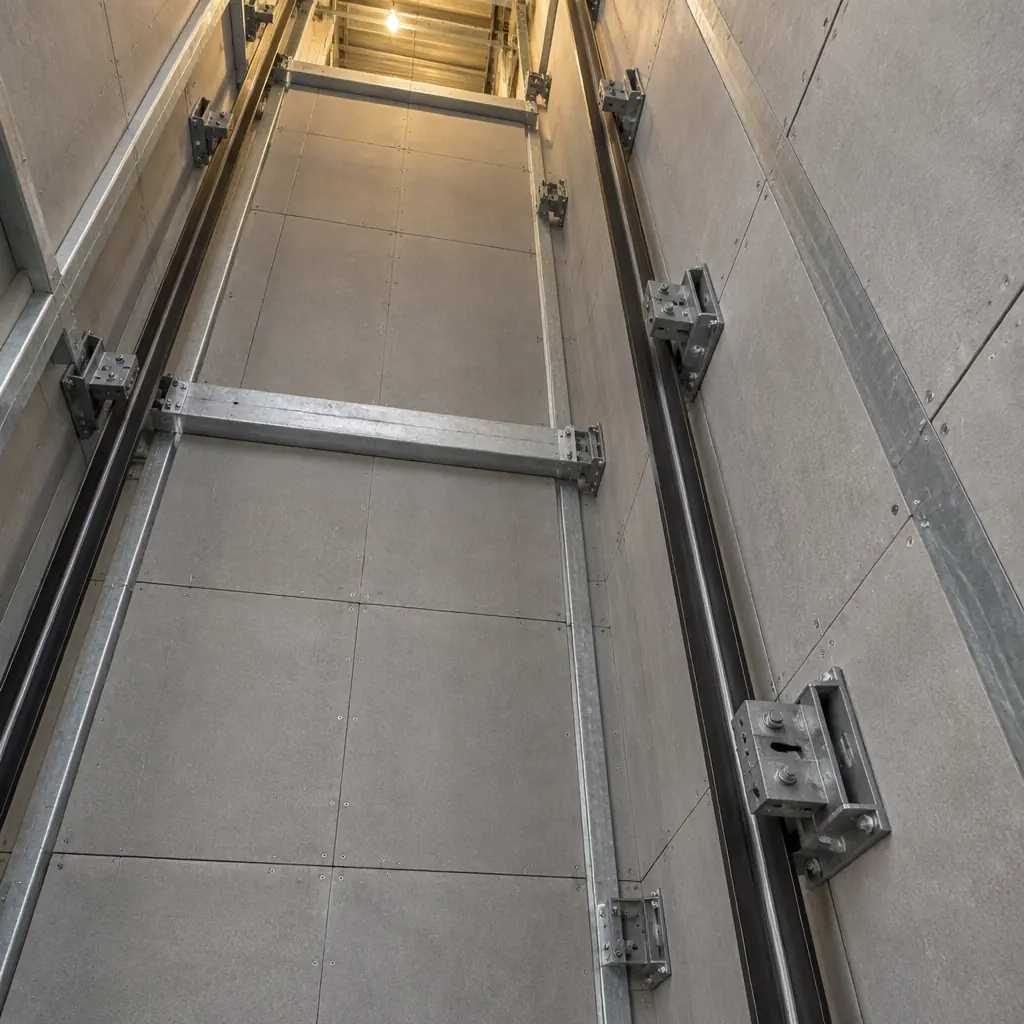
- Shaft walls and fire lining: a tested shaft-wall assembly on the shaft side, with the board joints and penetration seals installed in a controlled environment rather than at height.
- Lift guide rail brackets and divider beams: the embedded or bolted brackets that the lift installer will later align to, set in a jig to a tolerance the lift contractor can work with.
- Lobby and landing finishes: floor finishes, skirting, door frames and the lift landing door surrounds, protected for transport.
- Risers: the vertical sprinkler, drainage and electrical risers that pass through the core, with the floor-level penetrations and fire-stop collars already formed.
- Lighting and emergency lighting: stair and lobby luminaires, emergency fittings and their wiring to a core distribution board, tested at the factory.
What does not go in the factory is the lift itself, with one important exception. The lift car, machine, ropes and controller are installed by the lift contractor on site, because the lift is a piece of equipment with its own certification, its own warranty and its own commissioning regime. The exception is the machine-room-less (MRL) lift, where the machine sits inside the shaft head. On an MRL installation in a prefabricated core, the headroom, the machine beam and the controller location have to be designed into the core module rather than added afterwards, and that is a decision that belongs in the structural model, not in a lift contractor's shop drawing review three months before handover.
Why the Shaft Tolerance Decides Whether the Lift Works
An elevator is a machine that runs on two rails fixed to the shaft wall, and it is specified to run at a design speed with a design guide-rail load. Every lift manufacturer publishes the shaft tolerance their product needs. For a typical 1000 kg, 1.6 m/s traction lift, the practical allowances are a shaft plumbness of plus or minus 25 mm over the full travel, a shaft internal dimension tolerance of plus 25 mm and minus 0 mm, and a pit depth tolerance of plus 0 and minus 25 mm. Those are not generous numbers when they accumulate over six storeys.
Tolerance stack-up is where modular cores fail. Each core module is built to plus or minus 2 mm in the factory, which is excellent. But if six modules each sit 5 mm off the setting-out line in the same direction, the shaft is 30 mm out at the top before anyone measures a single guide rail. The lift installer then has three options: pack the rail brackets out, which reduces the clearance to the car and can void the lift's type approval; resize the car, which changes the capacity the building was designed around; or reject the shaft. All three cost money and two of them cost schedule. The full structural tolerance chain in a tall modular building is covered in our article on modular high-rise construction, and the core is the element where that chain has the least forgiveness.
| Shaft parameter | Typical lift manufacturer allowance | How a prefabricated core holds it | Failure mode if not controlled |
|---|---|---|---|
| Plumbness over full travel | ±25 mm | Laser setting-out of each core module against a fixed benchmark, surveyed at every level before the next module lands | Rail bracket packing, reduced car clearance, potential type-approval issue |
| Shaft internal width and depth | +25 / −0 mm | Jig-built shaft walls, dimension checked at the factory and again after the lift landing door surrounds are fitted | Shaft too small to accept the specified car; car downsize or shaft remediation |
| Pit depth | +0 / −25 mm | Pit formed by the foundation system, with the core base module set on a surveyed steel grillage rather than packed | Buffer stroke insufficient, pit deepening on site after the core is fixed |
| Headroom above top floor | Set by the lift type, 3.6-4.3 m for typical MRL traction | Head module dimensioned to the specified lift rather than to a generic allowance | Roof module and core head clash; late redesign of the top level |
| Verticality of guide rail fixing planes | ±3 mm per 5 m of rail | Brackets set in a factory jig to the surveyed shaft centreline | Rail realignment on site, vibration and noise in service |
The control that makes this work is not a tighter factory tolerance, because 2 mm is already better than any site can achieve. It is a survey gate at every level. Before the next core module is landed, the one below is surveyed against the project benchmark and the result is recorded. If a module is out, it is corrected at that level, when the correction costs a morning, rather than at the top, when it costs the lift contract. This is the same staging discipline we apply to MEP interfaces, described in modular MEP systems integration, applied to a vertical element.
Fire Separation and the Compliance Route for a Non-Concrete Shaft
A stair and lift shaft exists in the fire strategy for two reasons: it is an escape route, and it is a vertical void that would otherwise allow smoke and fire to spread between floors faster than any horizontal compartment could contain. In a cast-in-place core, a 2-hour fire resistance is achieved by the concrete itself and nobody questions it. In a steel core, fire resistance is an assembly property, and the assembly has to be a tested one, not an engineered judgement.
There are two acceptable routes, and the choice determines how much evidence the project needs at permitting. The first is a tested shaft-wall system: a proprietary board, spray or cementitious lining with a published fire resistance period, tested to the relevant standard for the destination market, with a tested detail for the joints, the penetration seals and the junctions to the floor slabs. The second is an engineered fire solution using a calculation method accepted by the authority having jurisdiction, which is a slower and more expensive route but sometimes the only one available when the core geometry is non-standard.
| Jurisdiction | Test standard for shaft and escape assemblies | What the permit reviewer typically asks for | Practical note for a prefabricated core |
|---|---|---|---|
| United States (IBC) | ASTM E119, with hose stream test for assemblies | Listing report covering the shaft wall, the joint detail and the floor junction | Shaft wall listing must cover the module-to-module joint, since that joint is unique to the modular build |
| United Kingdom and EU | BS EN 1364 / EN 13501-2 classification | Classification report with the supporting test evidence and extended application | Extended application reports are the usual gap for volumetric cores; confirm coverage before tender |
| Australia (NCC) | AS 1530.4 | Test report plus an assessment for the specific construction | Assessment is common and accepted; budget for the assessment fee and four to six weeks |
The modular-specific problem is not the shaft wall in isolation, it is the horizontal joint at every floor where one core module meets the next. A conventional shaft has continuous concrete; a modular shaft has a joint every 3 to 4 metres, and that joint has to be fire-stopped as part of the tested assembly rather than treated as a gap to be sealed on site. Our article on modular construction fire safety covers fire-rated assemblies in detail, and the companion piece on building envelope systems covers the related question of how the core enclosure meets the external wall at each level, which is where a surprising number of fire strategy queries originate.
The Two Lift Types That Change the Core Design
Lift selection is usually treated as a package decision made after the building design, and in a modular project that sequence is backwards. Two properties of the lift decide the core geometry, and both have to be fixed before the core module drawings are issued.
The first is machine-room-less versus machine-room. An MRL traction lift puts the machine in the shaft head and needs roughly 3.6 to 4.3 metres of headroom above the top floor level for a low-rise traction unit, with the controller in a landing-side cupboard or a shallow machine space. A hydraulic lift needs a machine room adjacent to the shaft at the lowest level, plus a jack space in the pit, and it is limited to roughly 15 to 18 metres of travel before the cost and the speed penalty make it uneconomic. On a six-storey building that difference decides whether the top level needs a 4.3 m structural head or can keep a standard floor-to-floor dimension.
The second is whether the lift is a fire-fighting lift. A fire-fighting or evacuation lift needs a protected lobby at every landing, a shaft construction that survives the fire scenario the escape route is designed for, a secondary power supply and a water-resistant car. Retrofitting a fire-fighting lift into a core designed without its lobby is close to impossible, because the lobby is floor area, and in a modular building floor area is modules. If the building's height or occupancy triggers a fire-fighting lift requirement in the destination code, that requirement has to be in the concept design, not the lift specification.
| Decision | Option A | Option B | Effect on the core module |
|---|---|---|---|
| Machine location | MRL, machine in shaft head | Machine room adjacent, or hydraulic with remote plant | MRL adds 3.6-4.3 m head module depth; machine room consumes a module or floor area at the base |
| Shaft dimensions | Standard car, e.g. 1000 kg / 13 person | Stretcher or bed car for healthcare | Healthcare lifts commonly need a 1.5 x 2.4 m car and a shaft roughly 2.6 x 2.9 m, which changes the core footprint for the whole building |
| Fire-fighting capability | Standard passenger lift | Fire-fighting lift with protected lobby | Protected lobby at every level consumes 6-10 m² of floor area per landing, taken from modules |
| Number of stops and travel | Low-rise, up to 18 m travel on hydraulic | Traction, unlimited travel with intermediate support | Long travel steers the choice to traction and therefore to a head module rather than a pit jack |
Site Sequence, When the Core Lands Relative to the Modules
The single most expensive mistake in a modular core programme is treating the core as something that happens after the modules are stacked. There are two viable sequences, and the choice depends on whether the core is the stability system.
Core-first sequence. The core is erected and surveyed to full height, or several storeys ahead of the modules, and the modules are then landed against it and tied in at each level. This is the right sequence when the core is cast-in-place or when the steel core is braced and acting as the stability system, because the modules need something to tie to. The cost is that the core is on the critical path at the start, so its own lead time, typically 10 to 14 weeks for a fabricated steel core including stairs and lining, has to be pulled forward into the design phase.
Module-first, core-fill sequence. Modules are stacked with the core void left open, and core modules are dropped into the void from above, floor by floor, using the same crane. This works when the modules themselves are stable without the core, which is the case for a well-braced volumetric system up to about four or five storeys on a braced frame. It removes the core from the start of the critical path and lets module production and core fabrication run in parallel, at the cost of a more demanding lift plan and a temporary weather protection problem over the open void.
Whichever sequence is used, three site gates have to be in the programme as hold points rather than as activities. The first is a pre-set survey of the foundation level at the core to confirm the pit depth and the base setting-out. The second is a per-level survey gate before the next core module lands. The third is a shaft handover survey, issued to the lift contractor as a documented record with plumbness, dimensions, pit depth and headroom measured and signed, because the lift installer will not start commissioning without it and will charge standing time if it is late. Lifting plans, crane selection and module weights for this sequence are covered in modular transportation and logistics, and the foundation side in modular building foundation systems.
What the Core Costs, and Why It Is the Line Item Buyers Miss
Buyers comparing a modular price to a site-built price usually compare cost per square metre of lettable floor, and the core is not lettable floor. It is gross area that produces no revenue and consumes a disproportionate share of the structure, the fire strategy and the lift budget. On a four-storey residential building, the core typically takes 8 to 12 percent of gross floor area. On a healthcare building with stretcher lifts and protected lobbies, that figure is 14 to 18 percent.
The cost of the core itself is best estimated as a range against gross floor area, because it scales with storeys and lift count rather than with module count. For a prefabricated steel core with one traction lift, precast stairs and a tested shaft lining, the structural and enclosure cost typically lands at 9 to 14 percent of total building cost for a four to six storey building. The lift package on top of that is a separate 3 to 6 percent depending on capacity, fire-fighting capability and finish level. A cast-in-place core usually costs less in materials and more in schedule and in the crane time it consumes while the site waits.
| Cost element | Share of core cost | What drives it | Where modular changes the number |
|---|---|---|---|
| Core structure, frame and shaft walls | 38-46% | Storeys, bracing requirement, shaft lining specification | Factory fabrication includes the fire lining and the penetrations, removing later site trade |
| Stairs, landings, balustrades | 12-16% | Number of flights, finish level, code geometry | Fitted and load-tested in the factory, no stair trade on site |
| Lift package, supply and install | 26-34% | Capacity, speed, fire-fighting capability, finishes | Unchanged by modularity, but shaft readiness is now a documented gate |
| Survey, setting-out and hold points | 3-5% | Storeys, number of survey gates | Higher than conventional because tolerance control is the risk being bought down |
| Lift commissioning and certification | 4-7% | Jurisdiction, inspection regime, test load availability | Can be brought forward if modules around the shaft are complete at commissioning |
The line that surprises buyers is the survey and hold point allowance. It is 3 to 5 percent of core cost that a conventional budget does not carry, and it exists because in a modular building the core tolerance risk is real and the control has to be paid for up front rather than discovered at the shaft handover. On a project where it is cut, the saving is smaller than the cost of a single rail realignment or a delayed lift commissioning. Whole-building cost structure is set out in modular versus traditional cost breakdown, and apartment-specific figures in the modular apartment buildings cost guide.
Design Decisions That Keep the Core Cheap
Most of the core cost is locked in before the first module drawing is issued, and the decisions that matter are few. Each of the following is worth more than any procurement negotiation on the lift package.
- Fix the lift type before the core is drawn. Capacity, car size and MRL versus machine room set the shaft dimensions and the head height. Deciding them after the core drawings are frozen means redesigning the top level and the pit.
- Stack the core on a single vertical alignment. A core that shifts position by one module bay between floors cannot be built from repeating core modules, and loses the factory advantage entirely.
- Put the risers in the core, not in the modules. Vertical distribution passing through the core keeps the module design repeatable and concentrates the fire-stopping in one surveyed element.
- Keep the fire-fighting lift decision at concept stage. A protected lobby is floor area, and floor area is modules. Adding it late costs a module per landing.
- Standardise the core module across floors. A typical floor module repeated from level two to the level below the head is the cheapest core; every variation adds a bespoke fabrication and a new survey risk.
- Book the shaft handover survey into the programme as a dated milestone. The lift contractor's mobilisation is priced against it, and a documented survey record is what converts a tolerance dispute into a non-event.
The same logic applies to the vertical transport question in accessible single-family and small multi-unit work, where a platform lift or a residential elevator is often added to a two-storey modular dwelling after the design is settled. A shaft reserve of roughly 1.5 x 1.6 m with a 2.4 m head, designed in at concept stage, costs very little; cutting one into a finished modular house costs a structural alteration and a re-clad wall. Our accessibility article, modular building accessibility and ADA compliance, covers the lift requirements that trigger this decision, and modular skilled nursing facilities covers the healthcare core requirements in more detail.
Frequently Asked Questions
Can an elevator be installed inside a fully prefabricated modular core?
The shaft, stairs, lining and guide rail brackets can be, but the lift itself is installed on site by the lift contractor. A prefabricated core with factory-set brackets and a surveyed shaft typically reduces lift installation time from around 13 to 17 weeks of sequential shaft work to 6 to 9 weeks of installation and commissioning, because the shaft is already built, lined and dimensionally verified when the lift team arrives.
What shaft tolerance does a modular core need to meet?
It has to meet the lift manufacturer's published tolerance, which for a typical 1000 kg traction lift is around plus or minus 25 mm plumbness over full travel, plus 25 and minus 0 mm on shaft dimensions, and minus 25 mm on pit depth. A factory-built core achieves 2 mm dimensional accuracy per module, so the controlling risk is setting-out accumulation between levels, not fabrication.
Is a steel core acceptable for a fire-rated stair and lift shaft?
Yes, provided the shaft wall is a tested assembly with published fire resistance covering the joints and the floor junctions, not a nominal board lining. In the US this means an ASTM E119 listing that covers the module-to-module joint. In the UK and EU it means an EN 13501-2 classification with an extended application report that covers the volumetric core construction.
How much floor area does the core take?
Typically 8 to 12 percent of gross floor area on a four-storey residential building, and 14 to 18 percent on a healthcare building with stretcher lifts and protected lobbies. That area produces no revenue, which is why core efficiency is one of the strongest arguments for a well-optimised modular layout on constrained urban sites.
When should the core be erected relative to the modules?
Core-first when the core is the stability system, because the modules need something to tie to. Module-first with a core fill when the modules are independently stable, which is usual up to about four or five storeys on a braced volumetric frame. The second sequence removes the core from the start of the critical path but demands a more detailed lift plan and temporary weather protection over the open void.
Planning a multi-storey modular building with a lift? Send us the floor plates and the intended lift specification and we will return the core configuration, the shaft tolerance schedule and the sequence that keeps the elevator off the critical path.